Quantify
 Used to extract
information from a 3D model and export the information in the form of
spreadsheets, databases, or word processing files. The report is based on
settings completed using this tool and component definitions defined in the
dataset.
Used to extract
information from a 3D model and export the information in the form of
spreadsheets, databases, or word processing files. The report is based on
settings completed using this tool and component definitions defined in the
dataset.

Using the Quantify tool, the application searches for and identifies every element in the model that matches the reference file and level criteria specified. Each element is processed as follows:
- The Part assignment of the element is identified.
- All Components linked to the Part definition are identified.
- The Formula of each Component as defined in the Part Definition is applied.
- The calculated value is entered into a report.
An Element is the physical object in the model.
The Part Definition links the Components to the element.
Components determine the unit of measurement and the unit price that is used to apply material takeoffs. Components are linked to Parts through a Formula.
The Formula determines how to physically measure the element. The Formula is critical to successful reporting. For example, a wall can be measured in three ways: the area for gypsum board, the volume for concrete, and the length for vinyl base.
For any quantification report to generate successfully without errors, the following must apply:
- Every element being calculated must have a Part assignment.
- Every Part that is assigned to an element must have at least one Component linked to it.
- Every Component that is linked to a Part must be linked through a valid Formula. For example, the height of a Solid cannot be measured, because a Solid is not parametric and therefore its intelligence does not include the concept of height.
To calculate quantities, the following process is executed for each Building and non-Building element:
- If a Part is not assigned to an element, a quantity is not generated for that element.
- If a Part is assigned to an element, Components linked to Parts are searched for. If Component is not found, an error message is generated in the <DGN file>.log file, which is located in the same directory as the design file.
- If one or more Components
are linked to a Part, the Formula of the Component is searched for.
If the Formula is not defined for the Component, an error message is generated in the <DGN file>.log file.
If the Formula is found, the quantity of the Component is calculated as specified by the Formula.
- The quantity is written to the report file
- The names of the spec text files that are linked to the Component are written to the <DGN file>.text file, which is located in the same directory as the design file.
- Starting from the Component, OpenBuildings Station Designer searches for the Parent Component until it finds a Parent Component that points to itself, which indicates the top of the tree structure. The data of the Parent Components is written to the report file.
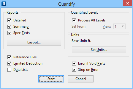
| Setting | Description |
|---|---|
| Reports group box | The following settings are available.
|
| Reference Files | Controls the files used to calculate the quantities of elements: |
| Limited Deduction | Controls the deductions of openings: |
| Data Lists | Controls the creation of a list of component definitions (<report name>.cmp) and of a list of part definitions (<report name>.par) that are used in the 3D model: |
| Quantified Levels group box | The following settings are available.
|
| Units group box | The following settings are available.
|
| Error if Void Parts | Controls the creation of a log file (<DGN file>.log) when a part in the model does not have a component linked to it: |
| Stop on Error | Controls processing when an error is found:
Errors are caused by the following:
The error messages are written to a log file (<DGN file>.log) which is located in the same directory as the design file. |
| Start | Generates a quantification report and closes the Quantify tool settings window. |
| Cancel | Closes the Quantify tool settings window without generating a report. |